
Articles
Self-Assembly Systems for Die Attachment: Technology Study – Surface Tension of liquid
Self-Assembly Systems for Die Attachment: Technology Study – Surface Tension of liquid
The reference discloses a self-aligning method, which is a type of hybrid self-aligning technique. Self-alignment of two semiconductors is achieved through the surface tension of water and the pick-and-place technique. First, water is applied to the surfaces of the two semiconductors, followed by the use of the pick-and-place technique.
Methods and Apparatus for Self-Aligning Batch Pick and Place Die Bonding
Summary of the Reference

Reference Provider: INTEL CORP
Summary: The application proposes a fluid dispensing assembly, first semiconductor, second semiconductor and pick and place assembly to self-align batch pick.
Self-Alignment Technique Used: The reference discloses a hybrid self-aligning technique that utilizes the surface tension of water along with the pick-and-place method to achieve sub-micron accuracy.
Mechanism:
- Dispensing fluid onto the hydrophilic surfaces of the first and second semiconductors.
- Using the pick-and-place technique to pick up the die and place it onto the second semiconductor.
- Self-alignment is achieved through capillary forces.
Key Benefits
- Improved Accuracy: Achieves sub-micron alignment precision.
- Fast Processing: The process performs alignment in less time compared to conventional approaches.
Application Areas: Semiconductor Chip
Objective: Addresses technical challenges related to accuracy, speed, and bonding multiple dies of different types and sizes in the self-aligning die bonding technique.
Reference Proposed: The application proposes a fluid dispensing assembly, first semiconductor, second semiconductor and pick and place assembly to self-align batch pick.
Structural Innovation:
- A fluid dispensing assembly to dispense fluid onto the surface of the first semiconductor wafer at the first time and onto the second semiconductor wafer at the second time.
- A pick-and-place assembly to simultaneously place the first batch of dies onto the first semiconductor wafer at the first time and the second batch of dies onto the second semiconductor wafer at the second time.
Mechanism of Improved Interaction:
- Fluid assembly: Applying fluid to the surfaces of the first and second semiconductor wafers at different times, respectively.
- Pick and place assembly: Using the pick-and-place technique to simultaneously place stacks of dies onto the first and second semiconductor wafers at different times.
- Capillary Action: The batch of dies on the first semiconductor wafer surface and the semiconductor wafer itself are self-aligned using capillary action.
Problem
- Slow Throughput:
- Existing batch transfer techniques only work for dies of the same type, size, and layout.
- Frequent Machinery Adjustments for different die sizes, types, and orientations
- Accuracy challenge
- High Cost.
Reference Proposed
Using a fluid assembly to apply fluid to the surfaces of two semiconductor wafers at different times and a pick-and-place assembly to simultaneously place stacks of dies onto the first and second semiconductor wafers at different times. Self-aligning the stack of dies on the first semiconductor wafer and another die on the second semiconductor wafer at different times using water capillary action.
Advantages
- The alignment of the semiconductor dies does not need to be as precise as many known pick and place processes.
- As the effect of plasma activation reduces over time, the time saved by picking and placing batches of dies can be beneficial, especially with very smaller die size (<3×3 mm).
- Capable of picking and placing any suitable arrangement of dies (or any suitable number, type, size, shape, and/or layout) without a redesign or reconfiguration of the pick-and-place assembly.
Self-alignment Process & Key Aspects
Self-Alignment process disclosed in this patent:
- Performing substrate treatment of the first wafer and second wafer independently (at the same time).
- Cutting the first wafer into multiple dies, then subjecting the dies and the second wafer to plasma activation.
- Parts of the second wafer's surface are made hydrophilic and hydrophobic.
- Using fluid assembly to place water droplets on the hydrophilic surface.
- Using pick-and-place to pick and place different types of dies simultaneously on the wafer.
- The dies will self-align on the second wafer due to the surface tension principle of water droplets.
Key aspect of the invention:
- To achieve the faster and high alignment accuracy (i.e. less than 1 micron), the reference discloses a pick and place and a fluid assembly. In some case the alignment accuracy achieved by this self-aligning process can be less than 200 nm.
- Precise alignment is not required while using the pick and place approach because, the surface tension of the fluid is used to align the die accurately and quickly.
- The reference uses two main assembly for self aligning the die on second wafer.
Pick and Place Assembly:
- The pick-and-place assembly includes a vacuum head for picking up the dies.
- The nozzle head has a plurality of holes, and the pick-and-place assembly uses a vacuum force to suction the dies to the vacuum head for picking and placing on the second wafer.
- Any die arrangement can be interchangeably used for pickup by the pick-and-place assembly.
- The pick-and-place assembly transfers all of the dies in the second die arrangement simultaneously.
- The first vacuum head includes openings that are of any shape (such as circular) and distributed (uniformly or non-uniformly) across the first vacuum head in a two-dimensional array.
Fluid Assembly:
- The fluid dispensing assembly enables and/or controls the dispensing of water droplets.
- The fluid assembly includes a nozzle head with a two-dimensional array of nozzles, spaced across the nozzle head, for dispensing water/fluid onto the wafer. The spacing of the nozzles can be uniform (evenly spaced) or non-uniform
- A plurality of valves dispense water/fluid from the fluid source onto the wafer. Each valve can be independently controlled and is operably connected to the nozzles.
- The fluid source may contain either a static supply (e.g., a reservoir with a predefined fluid amount) or a continuous supply of fluid. The fluid source is separate from but fluidly connected to the fluid dispensing assembly.
- The fluid dispenser controller circuitry controls the valves. The controller circuitry 1060 independently regulates each valve to control the amount of water/fluid dispensed through the nozzles. The valves function as on/off controls, either permitting or blocking fluid flow, with the dispensed amount determined by how long each valve remains open. The valves can also regulate fluid flow rate, controlling the dispensed volume based on both valve opening duration and flow rate.
- For larger hydrophilic regions (e.g., corresponding to larger die sizes), a greater volume of water is dispensed through the corresponding nozzle, while smaller regions receive a smaller volume, enabled by independent valve control.
- By using the pick-and-place assembly and fluid assembly as described above, it is possible to accelerate the self-alignment process of dies on wafers. Furthermore, this enables the use of dies and wafers of any shape and size for self-alignment. It is also applicable to smaller-scale structures. Additionally, able to achieve alignment accuracy of less than 1 micron.
Proof of Concept from Patent
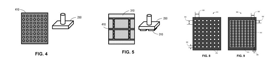
FIG. 4 is an example pick-and-place assembly 250 for picking up the example die arrangements 300, 310 of FIG. 3 . In some examples, the pick-and-place assembly 250 includes a vacuum head 410 for picking up the dies 135, 210, 220, 230. In some examples, the nozzle head has a plurality of holes and pick-and-place assembly 250 uses a vacuum force to suction the dies 135, 210, 220, 230 to the vacuum head 410 for picking and placing on the second wafer 130.
It should be understood that any die arrangement can be interchangeably used herein to be picked up by the pick-and-place assembly 250. The die arrangement 310 is suctioned to the vacuum head 410 via the vacuum force applied by the pick-and-place assembly 250 so that the die arrangement 310 can be picked up and placed on the second wafer 130. The vacuum head 410 corresponds in size (e.g., covers the boundary) defined by the fiducials 320, 330 of FIG. 3 . Thus, the vacuum head 410 may be sized so as to pick up the die arrangements defined by the fiducials 320, 330.
In some examples, the pick-and-place assembly 250 transfers all of the dies in the second die arrangement 310 simultaneously.
The first vacuum head 800 includes openings 810 are circular and distributed across the first vacuum head 800 in a two-dimensional array.
In other examples, the openings 810 can have any other suitable shape (e.g., square, oval, rectangular, triangular, oblong, elongate, etc.).
The openings 810 may be arranged at angles to define a triangular pattern or a honeycomb (hexagonal) pattern.
Source: https://patents.google.com/patent/US20240429199A1/en?oq=US2024429199A1
FIG. 10 is an example fluid dispensing assembly 1000 to dispense water on the example wafer 600 of FIG. 6 . That is, the example fluid dispensing assembly 1000 enables and/or controls the dispensing of the water droplets 700 discussed above in connection with FIG. 7 . A bottom view 1010 shows a nozzle head 1015 of the fluid dispensing assembly 1000. In this example, the nozzle head 1015 includes a two-dimensional array of nozzles 1020 spaced across the nozzle head 1015 for dispensing water/fluid onto the wafer 600. In some examples, the spacing of the nozzles 1020 is uniform (e.g., spaced evenly). In other examples, the spacing of the nozzles 1020 is non-uniform. Regardless of the particular size, number, and/or spacing of the nozzles 1020, in some examples, the nozzles 1020 are arranged to be sufficiently small and sufficiently close together to enable the application of water/fluid droplets to any suitable arrangement of hydrophilic regions within a single unit cell.
The fluid dispenser controller circuitry 1060 controls the valves 1040. In some examples, the fluid dispenser controller circuitry 1060 independently controls the valves 1040 to regulate the amount of water/fluid dispensed through the nozzles 1020. In some examples, the valves 1040 are on/off valves that either block or permit fluid to be dispensed through the nozzles 1020 such that the amount of water/fluid through a given valve 1040 is controlled by how long the valve 1040 is opened. In other examples, the valves 1040 can control the flow rate of fluid through ones of the nozzles 1020 such that the amount of water/fluid is based on both how long the valve 1040 is opened and the flow rate permitted by the open valve. In some examples, where one individual nozzle 1020 may be positioned over larger hydrophilic regions 620 (e.g., corresponding to a larger die size), a larger volume of water can be dispensed through the nozzle 1020. Likewise, with smaller hydrophilic regions 620, a smaller volume of water can be dispensed through the nozzle 1020 through the independent control of the valves 1040.
Electrical performance of self-assembly applied to die-to-wafer hybrid bonding CEA-Leti, Univ. Grenoble Alpes
The article discloses about the developments on self-assembly process. An electrical test vehicle was fabricated for self-assembly with daisy-chains and Kelvin structures designed with 6 µm pitch and hybrid bonding pad dimensions of 3μm. It further compares the performance of “self assembly process” with the “without self-assembly process” (standard Leti DTW process). The Characterizations of alignment performance, bonding quality and the electrical performance are demonstrated in the reference.
Self-Assembly Applied to Hybrid Bonding

|
Candidate for self assembly |
Water |
|
Surface energy |
72 mN/m |
|
Temperature |
25°C |
|
Annealing (temp) |
400°C |
|
Time period for annealing |
2 hours |
The CEA-Leti and Intel collaborated to develop a self-assembly process. This self-assembly process makes possible to place dies with a high throughput despite a coarse initial alignment. The principle of the self-assembly process is the use of a small drop of liquid to align a die to a target site through capillary forces. These forces occur when a liquid tends to minimize its surface energy through surface tension. In our case, the droplet tries to reduce liquid/air interface to reach an equilibrium state with a minimal surface energy. As a result, the die self-aligns on its bonding site. Water is an excellent candidate for self-assembly process thanks to its surface energy of 72 mN/m at 25°C. It also plays a role in direct bonding mechanisms and its evaporation can be easily controlled in a monitored environment. After the droplet evaporation, a spontaneous adhesion occurs between dies and targets. Then an annealing at 400 °C - 2 hours is applied to permanently bond the two parts together with metallic and covalent bonds.
Evaluate the self-assembly process (Testing is performed on 40 dies)
|
Self assembly hybrid bonding |
38 dies have been successfully bonded |
|
Standard hybrid bonding process without self-assembly |
40 dies have been successfully bonded |
Alignment Accuracy
- Alignment distribution below 1 µm: Self-assembly hybrid bonding - 76%, Standard hybrid bonding - 96%
- Alignment distribution below 200nm: Self-assembly hybrid bonding - 22%, Standard hybrid bonding - 6%
Comment: The proportion of marks aligned below 1 µm is 76% and 96% respectively for self-assembly process and standard process. With self-assembly 22% of the marks are aligned below 200 nm, compared to 6% with standard bonding.
Electrical performance of self-assembly process
- Median resistance (Daisy Chain): Self-assembly hybrid bonding - 0.65 Ω, Standard hybrid bonding - 0.6 Ω
- Median resistance (Kelvin): Self-assembly hybrid bonding - 0.59 Ω, Standard hybrid bonding - 0.35 Ω
- Yield: Self-assembly hybrid bonding - 70%, Standard hybrid bonding - 45%
Comment: For example, on DC1 (100 links), the yield for 0.7 Ω is 70% with standard integration against 45% with self assembly process. In both integration, a loss of yield on the 50 000 links daisy-chain is observed. As it concerns Kelvin, the cumulative resistance both integration are shown in Fig.12. On self-aligned dies, the resistance is higher than with standard integration, 0.59 Ω compared 0.35 Ω for 70% of yield. With regard to the five electrical blocks, no difference has been found between them in terms of DC and Kelvin resistance and yield.
Alignment Accuracy
- Bonding defect: Self-assembly hybrid bonding - Higher, Standard hybrid bonding - Lower
Comment: Moreover, the number of bonding defects is higher withself-assembly bonding. In previous works, pure thermal silicon dioxide surface self-aligned do not exhibit such defectivity [9].
In this study, it was found that daisy-chain and Kelvin resistance values were similar between two integration methods: one with self-assembly and one using the DTW standard process. This indicates that self-assembly integration does not negatively impact resistance as compared to the standard process. The presence of water at the interface during self-assembly did not lead to additional copper oxidation, as confirmed by experimental results and previous chemical and physical characterizations.
However, bonding yield was lower with the self-assembly process. This was likely due to additional steps (photolithography, etching, stripping) that may degrade bonding surfaces, particularly the copper surfaces. In conclusion, while the self-assembly process is electrically viable and comparable to the standard process, it requires further refinement, especially regarding bonding quality and alignment precision, to be fully competitive.
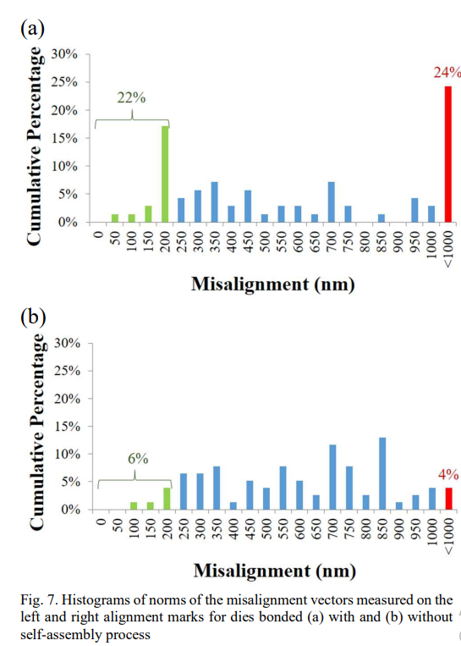
Alignment distribution below 1 µm, data are represented in Fig. 7 using a histogram of norms of the misalignment vectors
With self-assembly 22% of the marks are aligned below 200 nm, compared to 6% with standard bonding.
About Effectual Services
Effectual Services is an award-winning Intellectual Property (IP) management advisory & consulting firm offering IP intelligence to Fortune 500 companies, law firms, research institutes and universities, and venture capital firms/PE firms, globally. Through research & intelligence we help our clients in taking critical business decisions backed with credible data sources, which in turn helps them achieve their organisational goals, foster innovation and achieve milestones within timelines while optimising costs.
We are one of the largest IP & business intelligence providers, globally serving clients for over a decade now. Our multidisciplinary teams of subject matter experts have deep knowledge of best practices across industries, are adept with benchmarking quality standards and use a combination of human and machine intellect to deliver quality projects. Having a global footprint in over 5 countries helps us to bridge boundaries and work seamlessly across multiple time zones, thus living to the core of our philosophy - Innovation is global, so are we !!!
Solutions Driving Innovation & Intelligence


Enabling Fortune 500's, R&D Giants, Law firms, Universities, Research institutes & SME's Around The Globe Gather Intelligence That
Protects and Nurtures Innovation Through a Team of 250+ Techno Legal Professionals.